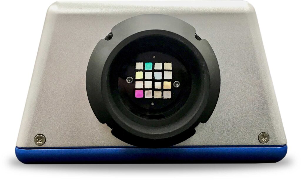
Multispectral imaging is a powerful tool used in a wide range of applications, from detecting bruised fruit to non-invasive monitoring of blood oxygenation levels. Also referred to as imaging spectroscopy, spectral imaging devices record spectral radiance signatures emanating from a surface that are a result of reflected, transmitted, or emitted light and are unique to a material and/or the state of a material that tells us something about it.
Similarly, light field or plenoptic imaging is an advanced technique that captures detailed information about the light field emanating from a source, including its direction and intensity. This technology has diverse applications, such as variable depth-of-field imaging, digital refocusing, and the creation of 3D models.
SOC’s LightShift™ Multispectral Video systems combine the capabilities of light field imaging—capturing direction and intensity information—with the radiance signatures of spectral imaging, making them highly versatile for material science applications. Using a patented plenoptic approach, these systems achieve this functionality with just a single camera and focal plane, offering a cost-effective solution. Unlike conventional snapshot cameras, LightShift™ systems function as full video-rate imagers. In this blog post, SOC explores the foundational concepts behind LightShift™ Imaging Systems and provides an analysis of the strengths and limitations of this innovative approach.
Basics of a Multispectral Color Imaging System
SOC’s LightShift™ imaging systems employs an innovative plenoptic, Division of Wavefront (DOW) technology for collecting video rate multispectral / multimodal image data. To understand how a division of wavefront system differs from a conventional camera, let’s start by looking at how a typical three-band multispectral (RGB) digital camera works when imaging a point source (Figure 1).

Imagine an infinitely small point source radiating white light as a spherical wavefront in this example. White light, in this case, is a continuum of wavelengths across the visible spectrum (400-700nm). In a grayscale camera, the portion of the wavefront radiated in the camera’s direction is captured by a lens that focuses the wavefront down onto an image plane. The point source illuminates just a single pixel in the image plane where its intensity is recorded.
In a well-designed system, only light from a specific wavelength range passes through and is recorded. Wavelengths outside that range are excluded. Typical grayscale cameras are designed to collect and record light in the 400-to-700 nm range. For a color camera, this range is subdivided into three regions: red, green, and blue, which correspond to the color receptors in the human eye (Figure 2).

Recording Color (3 Channel RGB)
Returning to our point source example, as the light from the point source is captured by the lens and falls on a pixel, it appears as a single point on a display whose brightness is proportional to the light being given off by the point source over the entire 400-700nm range. Since the light from all wavelengths is being collected, the color is unknown.
By adding two more cameras and placing color (RGB) filters over all three, we can now separately record the intensity of red, green, and blue and display color images. If necessary, the images from the three cameras must be registered spatially to complete the process, or the resulting RGB image will appear out of focus. The three-camera system also constitutes a plenoptic device, as each camera sees the light field from a slightly different angle.
However, using multiple cameras can be up to three times as expensive, and there is the registration issue. To address this, manufacturers found a clever way to use just one array. Using a Bayer filtering technique, also known as a Division of Focal Plane (DOFP) approach (Figure 3), R, G, and B filters are placed over adjacent pixels on the focal plane so there is only a slight displacement between bands. This technique is also being used to capture more than three colors.
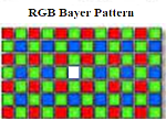
Classic Bayer pattern for producing color (multispectral) imaging a point source.
The cost and complexity are much lower since only a single focal plane is used. However, this approach also has some well-known shortcomings. In the case of our infinitely small point source, only a single pixel in the focal plane will be illuminated in a diffraction-limited camera. As shown in Figure 3, the white source is focused on a pixel with a blue filter over it, and hence, one might assume that our white point source is, in fact, blue, or if our point source is red, it would not appear at all. This effect is referred to as aliasing, and manufacturers have employed various techniques to mitigate it but have been unable to remove its effects completely.
LightShift’s Division of Wavefront Approach
So, how does a Division of Wavefront system work? Does it address the aliasing issue common to Bayer/Division of Focal plane approaches? Simply put, a Division of Wavefront system does. It operates by filtering different parts of the incoming light field at the front stop of the system to Divide the Wavefront into colors (Figure 4) before it reaches the focal plane, just as a three-camera system would. And unlike the division of the focal plane system, since each section of the wavefront can ‘see’ the point source, aliasing is not an issue.

In the LightShift™ imaging systems, the wavefront is optically divided into sections as it enters the lens using a microlens array (MLA) device, which reimages the wavefront at the front stop of the system onto the focal plane.
In a typical LightShift™ system, the MLA covers a 4×4 cell of pixels on the focal plane, where each pixel records light from one of sixteen different square sections of the incoming wavefront.
A 16-element filter array is placed at the front stop of the system where the wavefront enters. Each filter covers a section of the wavefront, which, in effect, creates a separate imaging system, each with a slightly different perspective, passing a specific color.
When the MLA reimages the wavefront/filter tray onto the 4×4 group of pixels on the focal plane (Figure 5), each pixel now records a separate color defined by the filter associated with that portion of the wavefront. This 4×4 set of pixels that represent the colors of the point source is hereafter referred to as a superpixel.
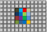
Filter array reimaged onto the focal plane array (referred to as a superpixel).
One benefit to the Division of Wavefront approach is that since the filters are large (10 mm square) and accessible through the filter tray, they can be replaced or modified on the fly to create a custom multispectral system that can even include polarization.
Data Collection
Figure 6 shows real data recorded by a LightShift™ Imaging system of a Macbeth color chart. This system covers the spectral range from 400 to 1000 nanometers, sometimes referred to as VNIR, because it includes the visible and some of the near-infrared (700-1000nm) portion of the spectrum.
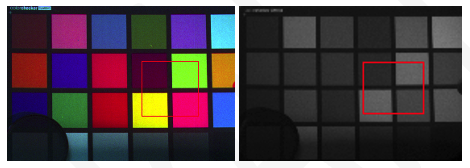
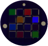
LightShift™ VNIR’s default filter tray (Figure 7) divides the VNIR spectrum into 16 equally spaced bands, but for this data collection, linear polarizers have been used in place of four color filters.
The raw image in Figure 6 with all bands displayed appears as a simple grayscale image captured by a standard monochrome camera, on closer examination (Figure 8), we begin to see the pattern of superpixels in the data.
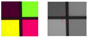
Zooming in even further (Figure 9), we can see the individual superpixels and the response of the individual color channels. Plotting the radiance values of four of these pixels corresponding to the individual colors on the Macbeth chart reveals the spectrum associated with the four panels.
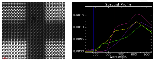
Zooming in even further (Figure 9), we can see the individual superpixels and the response of the individual color channels. Plotting the radiance values of four of these pixels corresponding to the individual colors on the Macbeth chart reveals the spectrum associated with the four panels.
Plenoptic Behavior
As mentioned earlier, LightShift™ is based on a plenoptic approach to dividing the wavefront. A typical LightShift™ system with 16 filters operates like 16 cameras with slightly different vantage points. As such, one can use parallax, i.e., the displacement in pixels for a point in the image from each of the 16 pseudo-cameras, to calculate the distance of a point in the object plane from the camera.

Focus at (31cm, 23cm, and 10cm) left to right.
In Figure 10, a single frame of data taken with the LightShift™ camera is shown. On the left, is a 3-band color image from the system which was set to bring the butterfly into focus (31 cm). Moving to the center image (23 cm), the coffee cup comes into focus when the bands are displaced slightly to compensate for the relative positions of the pseudo cameras when capturing the light field. On the right (10 cm) the pack of gum comes into focus requiring further displacement between band images. The colored border around each of the images gives a visual indication of the amount of displacement required between bands for a given distance. For the 31 cm image, where the system is in focus, border color is almost nonexistent. As we move closer, left to right, the displacement between bands becomes more exaggerated and we can see the effects of digitally refocusing within the image and along its borders. Conversely, using the displacement between bands at a point gives us the distance to that point.
Video-Rate Multimodal Imaging
One of the principal benefits of the Division of Wavefront approach is that it is possible to collect a complete multispectral image with each frame of the camera. This enables video rate spectral imaging at whatever frame rate the sensor is capable of. In addition, filters in the filter tray can be replaced by any optical element including polarizers.
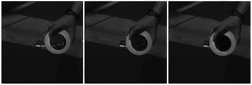
In Figure 11, a sunlit color chart is being imaged. The LightShift™ system has been configured to collect 12 color bands and 4 polarizations at 0-, 45-, 90- and 135-degree angles, sufficient to characterize the degree and angle of linear polarization.
On the left, a color image is produced by loading the pixel response of the sensor’s red, green, and blue channels into their respective colors on the display. And on the right, all 12-bands and 4 polarizations are shown simultaneously. The bottom four bands show the output from the four polarizers in the system.
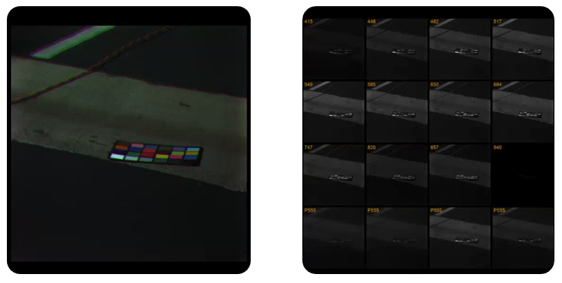
In Figure 12, the 90-degree, vertical polarization channel is displayed with a linear polarizer placed in front of the Macbeth chart and rotated through 0-, 45-, and 90-degree angles to demonstrate cross polarization.

Cost Effective Applications Across the Spectrum
One of the advantages of the Division of Wavefront approach is its flexibility and ease of implementation in other parts of the spectrum. Systems operating from the UV to far infrared have been developed to collect multispectral data by simply incorporating the appropriate camera/FPA, MLA, fore optic and filters into the design. In Figure 14, a LightShift™ system based on an InGaAs sensor operating in the 900 and 1700 nanometer region is used to visually differentiate between chemical compounds that both appear as white powders to the naked eye. By loading the relevant, short wave infrared channels into the RGB channels of a display, the two chemical compounds can be easily separated.
Unlike Division of Focal Plane systems, where thin film filters must be fabricated and applied at pixel scales directly to the focal plane, LightShift™ filters are large, placed at the front of the system, are interchangeable, and available off-the-shelf from several vendors. This attribute is particularly important at longer wavelengths where the height of dichroic filters can exceed the size of a pixel, resulting in ‘skyscraper’ filters and creating numerous mechanical and optical challenges.
In Figure 15, an instrument developed by SOC for the mid-wave (2-5 micron) infrared region is currently being used to monitor emissions from industrial flares for hydrocarbon content. The LightShift™ MWIR system, shown on the left, has been field-tested and is currently under evaluation by the EPA.

Continuously monitoring the combustion efficiency of an industrial flare has been a long-standing technological challenge. LightShift™ MWIR enables remote, automated direct measurement of industrial flare combustion efficiency (CE).

Conclusion
The basic theory and operating characteristics behind SOC’s LightShift™ Division of Wavefront (DOW) multispectral/multimodal imaging systems have been discussed. By its nature, DOW systems are immune to aliasing artifacts common in DOFP approaches that are critical in spectral imaging applications. Key benefits to the approach are video rate data collection, incorporation of depth information, on-the-fly spectral reconfiguration, and the ease of application to spectral bands outside of the visible range.
For further information on SOC’s LightShift™ product line please reach to our team at contact@surfaceoptics.com.


