What is BSDF?
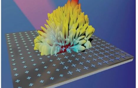
Light illuminating a surface may be reflected, transmitted or absorbed. The patterns of that interaction encode information about surface shape, material composition and structure. The quantitative representation of these patterns is the Bidirectional Scattering Distribution Function (BSDF).
BSDF radiometrically characterizes the scatter of optical radiation from and through a surface interface as a function of the angular positions of the incident and scattered beams. Due to the natural characteristics of materials such as surface roughness, ray propagation (e.g. scattering angle) can be understood as a random phenomenon satisfying the distribution of all angles described by the BSDF. In practice, BSDF is usually split into reflected and transmitted components, which are treated separately as the BRDF (Bidirectional Reflectance Distribution Function) and BTDF (Bidirectional Transmittance Distribution Function). Figure 1 illustrates the components of BSDF.
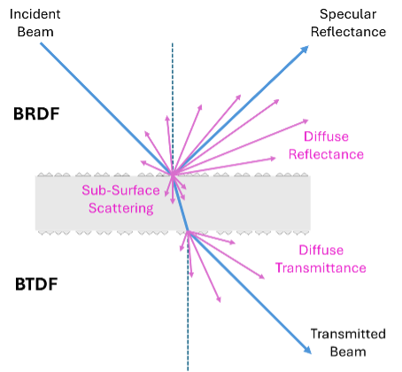
Figure 1 Components of BSDF.
BRDF describes the angular distribution of light scattered upward from a surface for a given incident light beam. It is a function of incident beam angle, reflected beam angle, polarization, wavelength, and intrinsic material properties. The 3-D spherical coordinate space of BRDF is illustrated in Figure 2, where θi is incident elevation, ϕi incident azimuth, θr is reflected elevation, and ϕr reflected azimuth. Elevation is defined relative to the zenith or sample surface normal.
BRDF is defined as the ratio of the reflected radiance Nr (W-m-2-sr-1) in a particular direction (θr, ϕr) to the incident irradiance Ni (W-m-2) with angular width δωi from direction (θi, ϕi). The units of the BRDF are inverse solid-angle (sr-1).

BRDF combines specular scattering in the direction of the angle mirroring the incident angle, diffuse scattering in all other directions above the surface, and potentially some fraction of sub-surface scattering, from structures within the material that may redirect transmitted light upwards. The integral of the BRDF over all reflected angles provides the dimensionless Directional Hemispherical Reflectance (DHR). Similarly, the integral of the BRDF over all incident angles gives the Hemispherical Directional Reflectance (HDR). The BRDF is invariant under the interchange of incident and reflected angles (reciprocity), therefore the HDR and DHR are equivalent and can be used interchangeably.
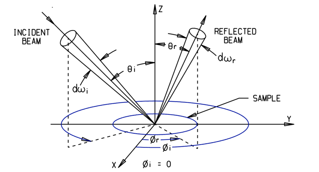
Figure 2 BRDF Geometry.
BRDF has been used by defense and aerospace industry for years to generate realistic scene imagery simulations for the simulation of sensors and detection of targets. SOC’s original founding fathers developed software and goniometric hardware to measure BRDF for use in the original NASA Apollo program to simulate the visual acquisition and docking of the lunar lander and the command module on the return trip to Earth. Much of that original hardware still resides at Surface Optics Corporation.
BTDF likewise describes the 3-D hemispherical distribution of light scattered through a surface. BTDF is often used to quantify the angular radiance of light emitting devices like LEDs or flat panel displays. It is also used as a metric of transmitted beam quality, where haze or stray light scattering through windows, lenses and other optical elements could degrade optical performance.
BRDF and BTDF Measurement Approaches
Bidirectional Reflectometry
A goniometric bidirectional reflectometer (BDR) uses a beam source like a laser or collimated blackbody to illuminate a sample from a selected incidence angle (θi, φi) while measuring scattered radiance with a radiometer at a chosen reflectance angle (θr, φr). In Surface Optics’ SOC-210 Bidirectional Reflectometer, shown in Figure 3, the source rotates through θi in a fixed plane of azimuth while the detector is free to sample both elevation θr and azimuth φr. The incident azimuth φi is achieved by a rotating sample stage. Goniometric BDR has a long track record represented by custom built research instruments in Government and Academic labs, and several ongoing commercial products that serve research and industrial markets. Consequently, it is often the standard technique against which other approaches are compared. Table 1 details technical specifications for the SOC-210 which are representative of a commercial high-resolution BDR.
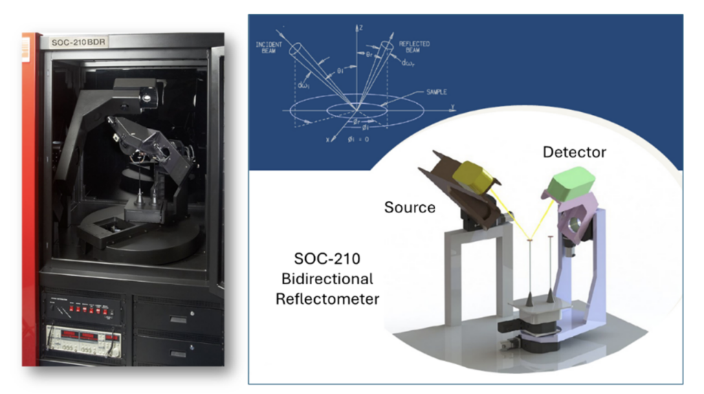
Figure 3 SOC-210 Bidirectional Reflectometer, a fully automated high-resolution goniometer.
| Table 1. Example Technical Specifications for SOC-210 Bidirectional Reflectometer | |
|---|---|
| Measurements | • Unpolarized BRDF • Bidirectional Transmittance Distribution Function (BTDF) |
| Spectral Range | • 0.40 to 14 micrometer wavelength – Customizable |
| Angular Coverage – accuracy 0.1˚ for each | • Incident polar: Theta I (ϴi = 0º to 85º) • Incident azimuthal: Phi I (фi = 0º to 360º) • Reflected polar: Theta R (ϴr = 0º to 85º) • Reflected azimuthal: Phi R (фr = 0º to 360º) |
| Spectral Filtering | Standard commercial off-the-shelf thin film 1 inch diameter bandpass filters. |
| Automation | θi, фi, θr, фr, source aperture, neutral density (ND) filter wheel, and sample/reference X-stage |
| Sources | Quartz halogen lamp, and/or silicon carbide glower |
| Detectors | Silicon, InGaAs, and InSb/MCT Stirling cooled – Customizable |
| Noise Floor | Less than 10-3 ster-1 or better (bandpass filter dependent). |
Goniometric BDR offers flexibility in choosing spectral range and polarization. High intensity sources and sensitive detectors with very low noise floor permit measurements on low reflectance samples such as CNT Ultra-blacks. Figure 4 shows an example of 3-D mapping of a SOC-210 full hemispherical BRDF measurement for a sample of diffuse gold.
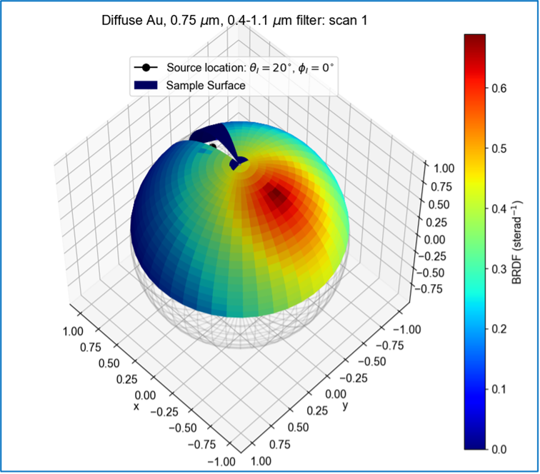
Figure 4 SOC-210 measurement of hemispherical BDR for a sample of diffuse gold.
Fully sampled BRDF can occupy a large data space. For example, at an angular resolution of 1 degree2, the hemisphere contains 32,760 possible reflectance samples for each incidence angle although only 30,600 are readily achievable in the SOC-210. A complete BRDF at this resolution would comprise 9.36 x 10⁸ data points. The SOC-210 and other modern BDRs feature angular resolution much better than 1 degree. Additionally, when BRDF is measured at multiple wavelengths and polarizations, the size of the possible data space scales further. As a result, measurement of full BRDF can be time consuming. Automation, combined with design of experiment principles, permits selective sampling of the BRDF to more rapidly acquire sufficient data to permit accurate fitting of BRDF model parameters.
Measurement Example 1: Low Scatter Satellite Mirror Film
In recent years, the rapid commercialization of satellite Internet communications has led to the deployment of thousands of satellite relay nodes in low earth orbit. Solar reflectance signatures from chassis and solar arrays can interfere with ground-based astronomy during early dark skies when the sun remains in view of satellites at near-grazing angles.
Levels of diffuse scattering from even the lowest reflectance ultra-black coatings are problematic, therefore the preferred solution is a mirror-like surface treatment that reflects all incident light away from ground observers. The critical requirement is for minimum diffuse scatter into non-specular angles.
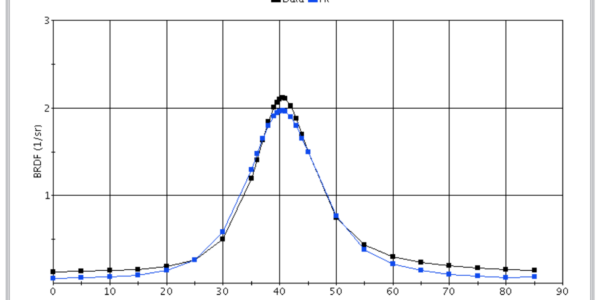
Figure 5 shows the BRDF of a mirror applique film intended for satellite signature reduction. The shaded region defines a specular reflectance cone angle of 67°±3°, which contains 90+% of the Total Integrated Scatter (TIS). Very little diffuse scatter occurs in earthward directions.
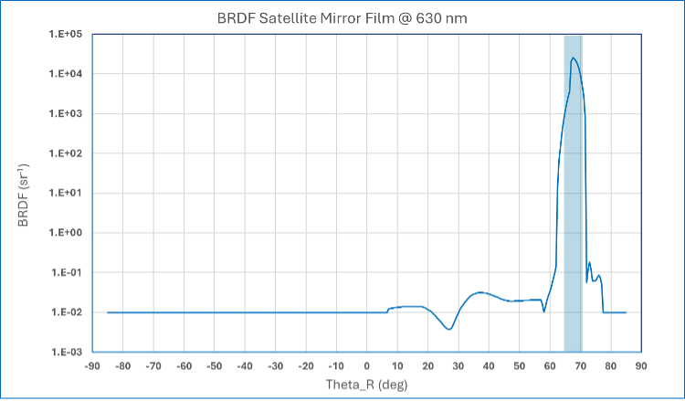
Figure 5 BRDF of satellite mirror film design with low levels of diffuse scattering.
Measurement Example 2: Selectively Diffuse Satellite Microwave Reflector Surfaces
Satellites often use parabolic microwave reflectors for Earth-Orbit communications. The large area cross section of these antennae presents the risk of severe damage during deployment if the antenna is oriented sun-ward and sunlight becomes focused on the microwave feed horn. The antenna must be conductive and mirror-like in the microwave region, with low α/ε to prevent distortion due to solar loading. One solution is to micro-roughen the reflector surface prior to metallization to make it diffusely scattering at solar wavelengths while remaining mirror-like at microwave wavelengths. The BRDF measurement is key to calibrating antenna surface processing by quantifying the fraction of solar energy that remains in the specular lobe of the reflection distribution function. Figure 6 shows the BRDF of a sample of metallized composite used in a satellite reflector application. In this example the shaded region defines a specular reflectance cone angle = 20°±3°, containing 40% of the Total Integrated Scatter. This surface is nevertheless highly specular at GHz frequencies. A slight increase in surface roughness is shown to reduce specular peak reflectance while increasing non-specular diffuse scattering. Note also that the specular lobe is approximately 50° wide as opposed to the focused 10° specular lobe shown in Figure 5.
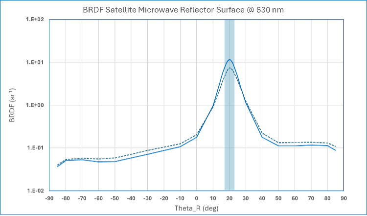
Figure 6 BRDF of satellite microwave reflector surface with controlled levels of surface roughening to reduce specular solar reflectance.
Image Based BRDF
An alternative to goniometric BDR is to use a high-resolution CCD camera to simultaneously capture scattered radiance across the whole hemisphere. In this approach, an ellipsoidal mirror above the sample focuses the reflectance distribution onto a camera detector array. Each pixel in the detector is associated with a different scattering angle from the sample, allowing the scattering distribution to be mapped from sample to detector. The angular resolution of the BRDF is directly proportional to the effective pixel resolution of the detector and optics.
For example, in the early 2000’s, Surface Optics Corporation working under contract with Boeing Defense and Space Group and AFRL developed a hand-held MWIR/LWIR Directional Reflectometer, shown in Figure 7, capable of simultaneously measuring both BRDF and HDR of a surface in-situ. Using Boeing’s patented angular imaging technique and a micro-bolometer array, the SOC-600 could fully map 3-5µm and 8-12µm scattering from a half-hemisphere above a surface with more than 30,000 angularly resolved points and update rates to 60 measurements per second. An offline computer then computed HDR from the measured BDR. Beam incidence elevation was variable from, θi = 0° to 85°, while scattering was measurable to nearly 90° off normal. A VNIR version of this device, called the SOC-610 was also proposed.
Each pixel in the “angular image” formed on the array corresponds to a small range of scattering angles relative to the illuminated spot on the measured surface. If the detector response is known for each pixel, the images may be interpreted as a quantitative measurement of the angular distribution of the reflected light. Alternatively, dividing by the incident intensity of the illuminating beam, the image can be interpreted as revealing the angular distribution of reflectance from the sample. Summing over the image determines the total reflectance, though this is complicated by the fact that not all scattered rays are captured in the image. Figure 8 illustrates an SOC-600 measurement of Navy gray paint measured at 50° angle of incidence in the 3-5µmm band. BRDF calculated from the imaging detector compared well to SOC’s goniometric BDR analysis.
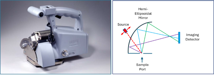
Figure 7 SOC-600 MWIR/LWIR HDR-BRDF Reflectometer, and optical path mapping directional reflectance to the camera image plane.
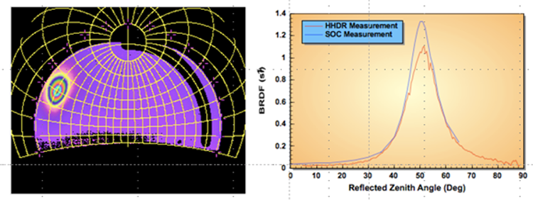
Figure 8 SOC-600 3-5μm angular image of gray paint at 50° incidence angle. SOC-600 BRDF is compared to SOC-200 goniometric BRDF of the same sample.
A later development was the catadioptric Imaging Sphere patented by Philips and commercialized by Radiant. A notable difference compared to the SOC-600 was that the hemisphere reflector surface was Lambertian rather than specular, so it effectively acted as a projection screen instead of a mirror. Using a secondary mirror the camera was able to image the hemisphere, as shown in Figure 9. The Imaging Sphere was uniquely suited for measurement of BTDF, and indeed it was originally developed for analysis of the angular light output of LEDs and flat panel displays. Unfortunately, neither the SOC-600 nor Imaging Sphere are presently commercially available.

Figure 9 Philips/Radiant Catadioptric Imaging Sphere.
In computer-aided design and media creation, it is essential to accurately model the ‘textures’ of surfaces. Recent approaches to Imaging BRDF have therefore been focused on photorealistic “Appearance Capture” or Spatially Varying BRDF (SVBRDF). This is sometimes also termed the Bidirectional Texture Function (BTF). A texture may embody a pattern that varies over area, therefore the definition of BRDF is extended to include spatial dimensions:

An SVBRDF may be regarded as an image with a different multispectral BSDF associated to each pixel. Measurement of SVBRDF requires knowledge of angular illumination and reflectance, plus the direction of the surface normal at each image pixel. Thus, the physical geometry of the surface texture is essential. Methods generally involve capture of multiple images at different camera locations, either from a single moving camera or multiple cameras fixed on a hemispherical support. Both movable single light source and fixed light source array illumination has been used. The surface under test may have a defined cylindrical or spherical shape, and it may also rotate through multiple dimensions. Photogrammetry performed on the image dataset permits pixel alignment between images and height map calculation. All these permutations permit sampling of the possible angular combinations of source-target-detector placement at each pixel. Figure 10 illustrates some of these basic elements of SVBRDF capture.
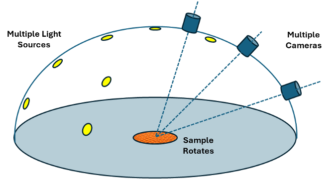
Figure 10 Multi-camera approach for multiple source-target-detector sampled image capture used to compile SVBRDF data sets
SVBRDFs are calculated by fitting parameters of analytical BRDF models (e.g. the Ward BRDF) to the individual pixels of image-based measurements. Conventionally performed by non-linear optimization, the computation requires long processing times on the order of several hours for one material. Using SVBRDF databases containing many material examples, researchers at University of Bonn have been able to apply deep learning to reduce fitting times to several minutes. The X-Rite/Pantone TAC7 Appearance Capture workflow is a commercial implementation of this research.
Conclusions
The best approach for BRDF measurement depends largely on end-use. For quantitative engineering or radiometric requirements, goniometric BDR gives highly accurate analysis of angular scattering and surface roughness effects. Alternatively, imaging BRDF for appearance capture provides photorealistic representation of complex surface textures for applications in design, architecture and media creation.

