Spectrally tailored physical vapor deposition (PVD) coatings are a mainstay for optical/thermal control in aerospace and solar energy applications. They are commonly applied directly to component structures or a polymer film that can be mounted with an adhesive. Neither approach is easy to implement for application surfaces with a very large size or complex geometry. An alternative is to turn the PVD film into flake pigment for paint that can be applied using conventional spray equipment.
SOC manufactures multilayer flake pigment for spectrally tailored paints (STP). A release layer applied before the deposition of PVD multilayers permits the stack to be stripped from the carrier web, pulverized, and size-classified. When spray applied, pigment flakes align in stacked layers as the paint film loses solvent and shrinks in volume. The optical performance of the spectrally tailored paint can be estimated based on models of the paint structure.
Paint Structure with Flake Pigments
A paint film is a matrix consisting of binder and pigment. Spectrally selective paints may contain reflective flake pigments plus a mixture of small color-scattering or absorbing co-pigments. Co-pigments primarily control Visible and NIR reflectance, while flake pigments modify coating reflectance out into the thermal IR. This balanced structure allows for controlled reflectance properties across different spectral regions, making it highly useful for thermal and optical regulation. Figure 1, at the right, illustrates structural characteristics including:
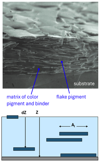
- Random spatial distribution of flakes within the matrix.
- Orientation of flakes is generally near-normal to the paint surface, although variation can occur based on pigment loading, flake size, and coating application method.
Key considerations for formulation are pigment spectral reflectance and pigment volume concentration (PVC). PVC is the unit area ratio of pigment volume to total film volume and is directly related to pigment number density. There is a PVC value for each pigment type in the formulation. Flake pigment effects on paint performance can be approximated based on a spatial statistical model that averages the depth-weighted photon-free path as a function of flake PVC.
Flake Pigment Model Assumptions
- SCATCAD Radiative transfer modified to sum over geometric cross-section or fractional area (Ai) for flakes at random depths (dZ), in a film with total thickness Z. Flake thickness defines the number of strata that flakes can occupy. Flakes in different strata can overlap and block the photon path. An empirical absorption coefficient accounts for path attenuation by binder and co-pigments.
- Flake geometric cross-section is typically much larger than IR wavelengths of interest (Ai >> λ).
- Flake optical properties modeled using Fresnel reflectance for semi-infinite surfaces.
- Edge scattering and light trapping effects were neglected for the first approximation.
Binder and Co-Pigment
- Co-pigment diameter is typically on the order of Visible/NIR wavelengths (Ai ~ λ), taking advantage of enhanced multiple scattering for maximum reflectivity.
- At IR wavelengths, binder and co-pigment form an effective medium with reduced scattering and composite absorption.
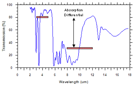
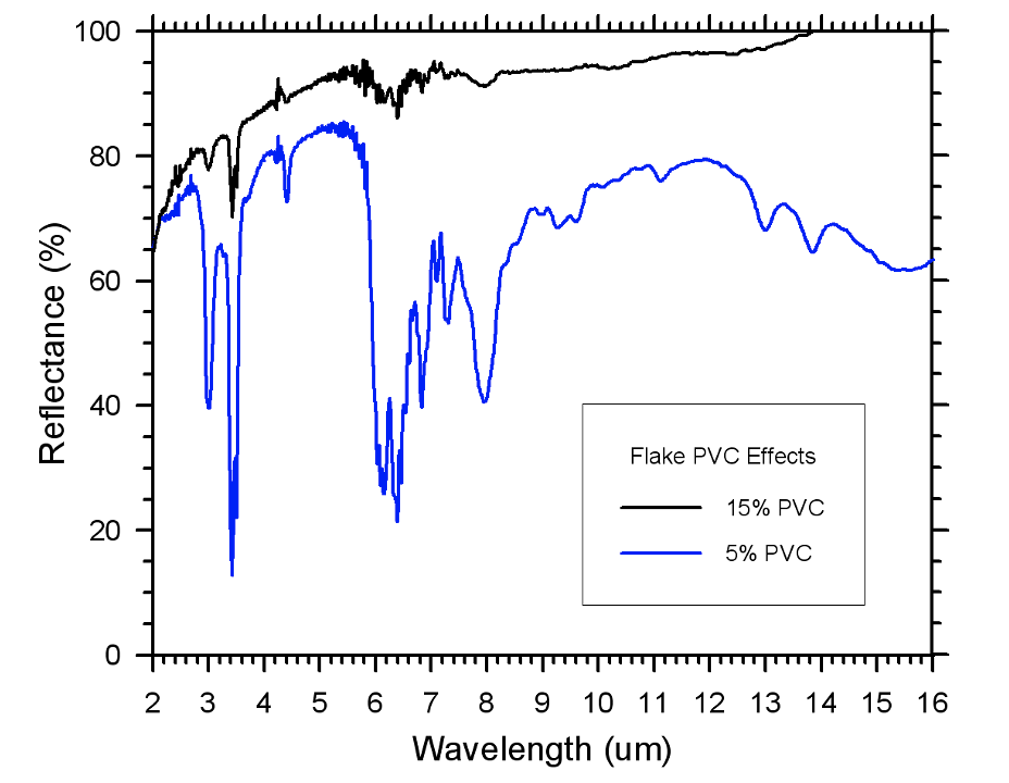
The epoxy binder transmission spectrum shown in Figure 2 contrasts the differences in IR absorption for MWIR and LWIR spectral bands. Where the MWIR spectrum of organic and dielectric materials is relatively free of vibrational bands, significant LWIR absorption is associated with chemical structures that are necessary for binder physical performance. This can present a challenge when selecting the right binder for a spectrally selective paint.
A model analysis of two grades of commercial aluminum pigment serves to illustrate this. An automotive grade ‘silver dollar’ pigment 20 mm diameter x 100 nm thick is compared with PVD aluminum with 10 mm diameter x 20 nm thickness. Note the contrast in surface textures shown in Figure 3, particularly the visible edges of the larger and thicker flake pigment.

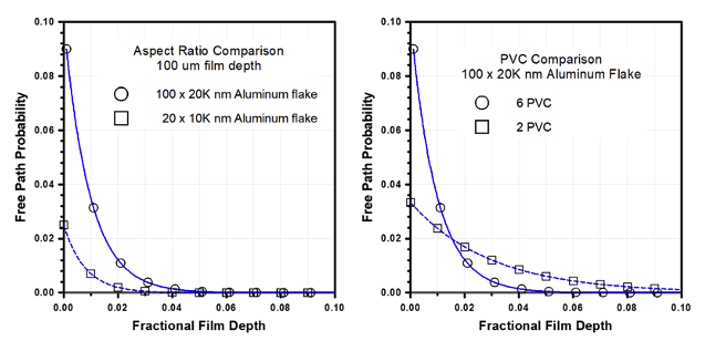
Plots in Figure 4 correlate the probability of a photon reaching a reflective flake surface at a given fractional depth in the paint film, independent of absorption or scattering loss. For flake formulations with the same PVC but different sizes, the model predicts a maximum penetration depth of 6% for the larger aluminum flake and 4% for the PVD aluminum flake. For the large pigment at different PVC, lower PVC allows much deeper photon penetration into the paint before reflection. Reflectance will thus be attenuated by scattering and binder absorption in the matrix between the flakes.
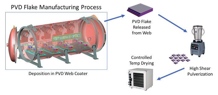
Production of Spectrally Tailored Flake Pigments
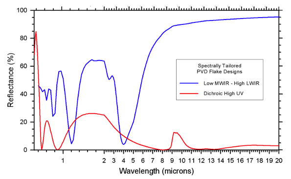
Spectrally tailored flake starts with a conventional vacuum deposition of a multilayer PVD film that meets the optical performance requirements of the end-use application, such as wavelength-specific reflectance or absorption. Figure 5 shows the measured reflectance of two example PVD film designs. Edge effects and multipath loss between flakes make it difficult for paints to match the reflectance levels of the constituent pigment. Pigment reflectance, therefore, usually needs to be engineered higher to offset the performance loss.
For the manufacture of flake, the PVD film is coated on a carrier web pre-treated with a release layer, as shown in Figure 6. The released film is subjected to high shear pulverization, dried, and sieved to the appropriate size for the intended application. Note that the flake pigment optical design needs to be symmetric because either side of the flake could be visible in the applied paint.
Effects of Formulation on Spectrally Tailored Paint Reflectance
Measured reflectance of a series of coatings formulated with PVD flake pigment illustrate the interdependent effects of flake size, PVC and binder absorption described by the paint model. The pigments in these examples were made from multilayer PVD film designed to have broadband high IR reflectance. Figure 7 compares polyurethane-based flake coatings formulated with the same PVC but with flakes sieved to different size ranges. As flake diameter increases, tiling efficiency also increases and losses due to flake edge scatter and binder absorption are reduced. Flakes with diameter that is a significant fraction of the final paint film thickness will tend to be less randomly oriented. The upper limit for flake size is typically defined by paint application considerations such as spray gun aperture.

Figure 8 demonstrates the effect of flake PVC on the optical performance of the paint film. Photon-free path probability through the binder matrix is limited with increasing PVC, as illustrated in Figure 4. Reflectance losses due to binder absorption are, therefore, also limited as paint reflectance converges toward the baseline reflectance of the PVD film design. It is important to note, however, that for most paint applications there is a critical pigment volume concentration (CPVC) for every paint formulation above which paint physical performance attributes like adhesion and flexibility cannot be met. This is one of the performance trades that need to be accommodated in the design of spectrally tailored paint.
Paints must meet operational requirements for adhesion and abrasion, temperature, and weather resistance. Formulations must be tailored to be sprayable, producing defect-free films with controlled application thickness. Solvents in the paint system must be compatible with substrates. Binder selection must, therefore, strike a balance between physical and optical performance. Figure 9 compares the optical performance of two different candidate binders in flake pigment formulations.

The polyurethane binder in Figure 9 was selected primarily for optical performance – low absorption in both MWIR and LWIR regions. The acrylic binder shown here may be a better choice for physical performance, but it also demonstrates how a polymer design that provides superior physical properties can have less favorable optical properties for a given spectrally tailored paint application. As with many conventional paint binder systems, this acrylic exhibited a significant differential in absorption between MWIR and LWIR. A proper choice of flake size and PVC can help overcome some of the challenges in formulating spectrally tailored paints using these polymer systems.
Model analysis in Figure 10 shows how differential binder absorption coefficients in MWIR and LWIR can affect the reflectance of flake-based paints. On the left are model and measured data for an epoxy paint formulation using broadband IR reflective flake pigment. It is not surprising that paint reflectance was higher at MWIR wavelengths where binder absorption was low. Model absorption coefficients for the binder matrix were fit to the measured data.
What kind of optical performance could be expected in this binder matrix using spectrally tailored PVD flake, for example, the low MWIR reflectance design shown in Figure 5?
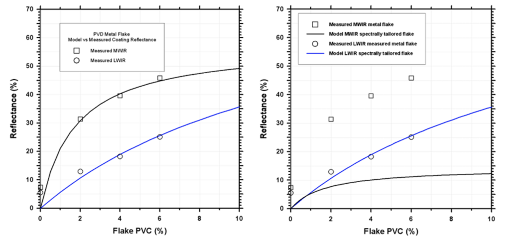
Figure 10. Model fit to measured reflectance of broadband IR reflective flake coatings, compared to predicted MWIR reflectance for spectrally tailored low-MWIR reflective flake coatings. Note that LWIR reflectance is virtually unchanged.
At right, the model predicts equivalent LWIR performance for the PVD flake, not surprising because pigment LWIR reflectance and size range for the two flakes are approximately the same. For both paints, LWIR reflectance should also increase as a function of PVC. By contrast, the model predicts nearly constant low MWIR reflectance for spectrally tailored paint across the same PVC range.
Figure 11 shows the measured spectral reflectance of low-MWIR coating formulations with increasing flake content. As the model suggests, LWIR reflectance averages were directly proportional to flake PVC, while MWIR reflectance averages increased only slightly. Note that at 20% PVC binder absorption had been largely suppressed, suggesting this level was close to the CPVC value for these formulations.
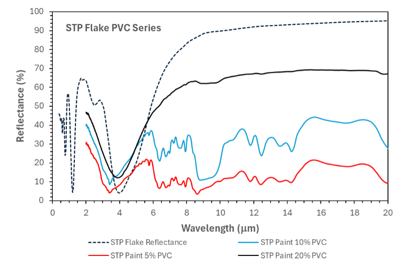
Figure 11. PVC series with low-MWIR/high-LWIR reflectance PVD flake pigment in an epoxy binder. The dashed line is the design reflectance of the PVD multilayer.
Key Findings from the Model
- The optical signature from color pigments and binder is primarily localized within the top 5% of the film thickness.
- Large flake diameter and high flake PVC limit photon penetration, resulting in higher reflectance—an outcome confirmed by experimental measurements.
- Lower flake PVC leads to significant photon penetration, increasing absorption due to binder and color pigment signatures.
- The model correlates well with measured paint formulations at various PVC loadings.
- A semi-empirical approach accounts for effective optical losses due to internal scattering and absorption, conceptually similar to Kubelka-Munk theory.
- Statistical modeling of flake area and depth distributions accurately reproduces MWIR/LWIR reflectance trends observed in studies of paints formulated with several different binders.
Conclusion
The use of spectrally selective PVD coatings in the form of flake pigments offers a versatile solution for complex geometries and large surfaces where traditional deposition methods are impractical. Through careful formulation and modeling, these coatings can be fine-tuned to provide precise optical and thermal control, making them invaluable for applications in aerospace, solar energy, and beyond.